- Home
- Braking Resistors
- Products
- Thermal Management
- Heaters
- Aluminium Foil Heaters - IP68
- Cartridge Heaters
- Cast Heaters
- Ceramic Knuckle Heaters
- Coil Heaters, Coiled Heater Bands and Nozzle Heaters
- Custom Heaters
- Drum Heaters
- Finned Air Heaters
- Flanged Heaters
- Flat Tubular Heaters
- Flexible Tubular Heaters
- Heating Cables, Crankcase Heater
- Immersion Heaters
- Mica Insulated Heaters, Mica Band Heaters, Mica Plate Heaters
- PTC Self-regulating Heating Elements
- Silicone Mat Heaters, Wire Wound, Etched Foil
- Tape Heaters
- Thick Film Heating Elements
- Tubular Heaters
- Railway Heaters & Relays
- Cable Management
- Electrical Control Gear
- Machine Safety
- Contact
Braking Resistors - Power Resistor
Braking Resistors
We have used our heating element expertise to offer a complete range of highly compacted braking/retardation resistors with the highest performance levels. Our resistors offer the best possible performance with the smallest physical size to maximum wattage ratio due to the high level of heat dissipation.
The braking/retardation resistors can be supplied with thermal switches and safety cut outs if required and in caged or flat section.
Applications include the smoothing of power peaks for electronic speed controllers and frequency transformers in the manufacturing industry, electrical industry, apparatus construction, inverters, speed controllers markets.
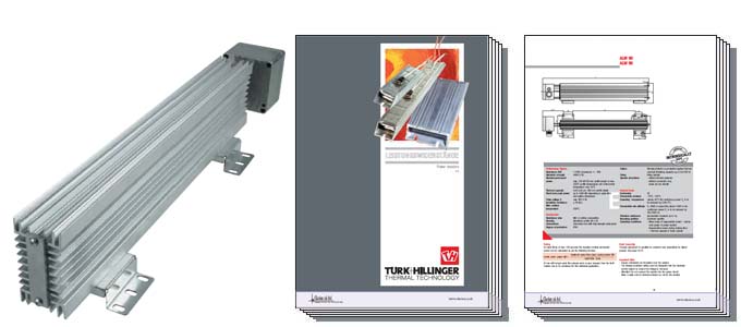
Power Resistor
Power resistors are designed to smooth peaks within electronic circuits. Due to the highly compacted construction the resistors have a good thermal conductivity. The heat generated within the resistor is easily conducted to the outer sheath and also in case of restricted space a maximum discharge of energy is reached. Turk and Hillinger supplies power resistors in 4 types of construction:
- High density cartridge heaters type HLP (see leaflet HLP, but with a dielectric strength up to 4100 V DC)
- Aluminium power resistors type ALW 40, ALW 70, ALW 80, ALW 90
- Flat brake resistors with steel housing type FBW
- Power resistors type RHK
Braking retardation resistors (PDF datasheet)Product enquiry and further information (Contact us form)
Through the highly compacted construction
- High thermal capacity
- High durability
- 100% vibration resistance
- Optimum heat dissipation from the resistance wire over the sheath surface to the environment
- Higher power capacity compared to uncompacted resistors
General Items
- Electrical safety
- Easy mounting
- If required the power input can be increased arbitrarily through serial or parallel connection of the power resistors
- The different construction types allow a low-priced solution for the individual problem
Insulation resistance
- ≥ 10 MΩ
Pulse voltage
- max. 970 V DC
Dielectric strength
- 1800 V AC / 2600 V DC
- 2800 V AC / 4000 V DC
Quality control
- conform to VDE 0700
Conformity
- CE, UL-approval on request
Permissible ambient operating temperature
- -10°C…+55°C, (above 45°C the continuous power Pn is to be reduced by 2.5%/°C)
Permissible site altitude
- 0…4000 m above sea level (above 1000 m the continuous power Pn is to be reduced by 5%/1000 m)
Intrinsic Safety
On request the power resistors ALW can be fittet with an unique patented internal thermal fuse. The thermal fuse will activate if the resistor experiences critically high temperatures. The maximum voltage is 970 V DC for ALW70, ALW90 and FBW resistors. If an internal thermal fuse is fitted then the maximum surface temperature may need to be reduced depending on the individual application.
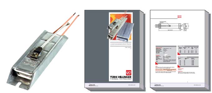
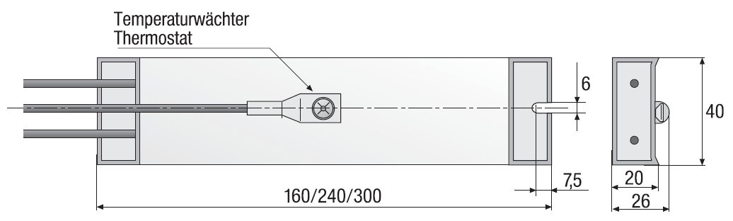
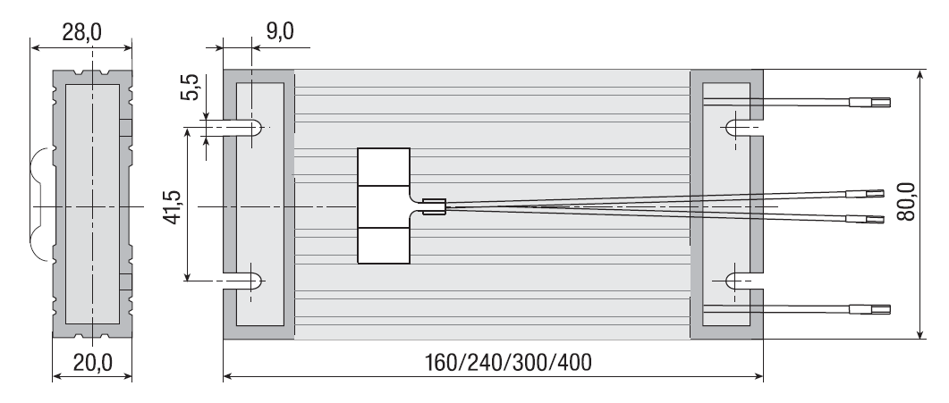
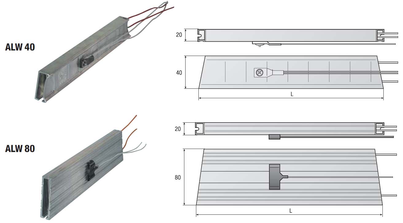
ALW 40
ALW 40 (PDF datasheet)Product enquiry and further information (Contact us form)
Resistance R20
- 1-1000 Ω, tolerance +/- 10%
Dielectric strength
- 4000 V DC
Pulse voltage U
- max 970 V DC
Insulation resistance
- ≥ 10 MΩ
Max. surface temperature
- 250°C
Resistance wire
- NiCr or similar composition
Housing
- Aluminium Profile 40 x 20
Connections
- PTFE insulated lead
Degree of protection
- IP23
Option
- Bimetal protector as protection against thermal overload (Breaking capacity e.g. 0,5 A/230 V)
Fixing
- directly with screws M5
Technical Data
- Short-term peak power W
- Nominal perm. power W
- Length
- Width x Height mm
- Thermal capacity kJ/K
- 2600
- 35
- 160
- 40 x 20
- 0,21
- 4000
- 60
- 240
- 40 x 20
- 0,34
- 5000
- 80
- 300
- 40 x 20
- 0,43
Stock Type Resistors
- Length (L) mm
- Resistance (R) (Ohm)
- Article No. with thermostat
- 160
- 200
- 077006
- 240
- 100
- 077005
- 240
- 370
- 077004
- 240
- 470
- 077003
- 300
- 82
- 077008
- 300
- 240
- 077007
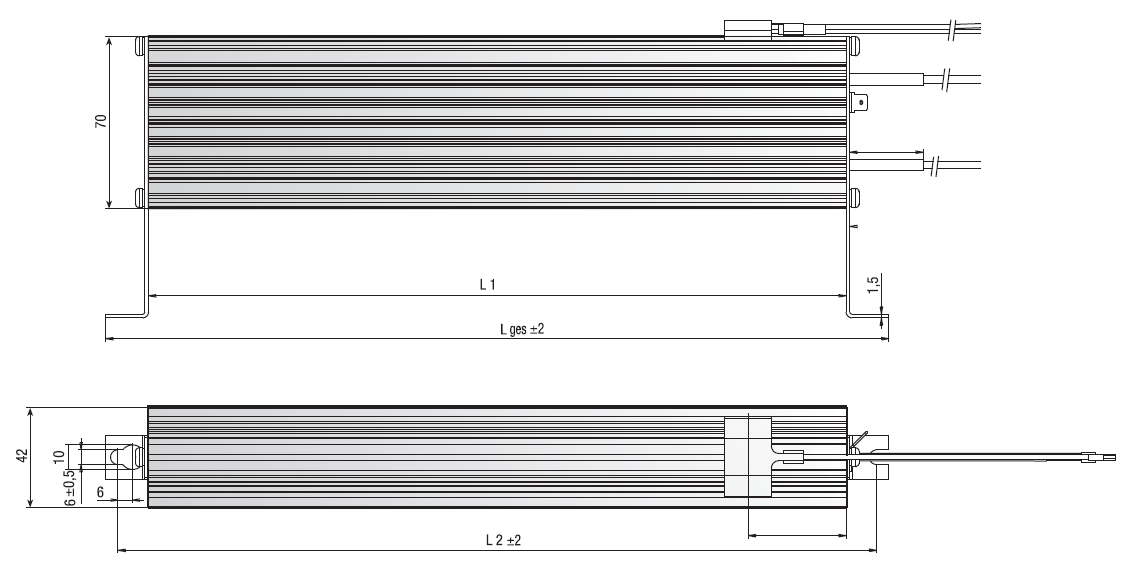
ALW 70
ALW 70 (PDF datasheet)Product enquiry and further information (Contact us form)
Resistance R20
- 1-1000 Ω, tolerance +/- 10%
Dielectric strength
- 4000 V DC
Nominal permanent power
- max. 100 W/100 mm profile length at max. 250°C profile temperature and environment temperature max. 45°C
Thermal capacity
- 0,36 kJ/K pro 100 mm profile length
Short term peak power
- up to 300 kW depending on pulse time and resistor dimensions
Pulse voltage U
- max. 970 V DC
Insulation resistance
- ≥ 10 MΩ
Max. surface temperature
- 250°C
Resistance wire
- NiCr or similar composition
Housing
- Aluminium profile 70 x 42
Connections
- PTFE insulated lead
Degree of protection
- IP23
Option
- Bimetal protector as protection against thermal overload (Breaking capacity e.g. 0,5 A/230 V)
Fixing
- fixing bracket
Conformity
- CE
Permissible ambient
- -10°C…+55°C
Operating temperature
- (above 45°C the continuous power Pn is to be reduced by 2,5%/°C)
Permissible site altitude
- 0…4000 m above NN, (above 1000 m the continuous power Pn is to be reduced by 5%/1000 m)
Vibration resistance
- Acceleration resistant up to 1g
Operating conditions
- Mean value of regenerative power < permanent power of power resistor
- Regenerative power during braking time < thermal capacity of brake resistor
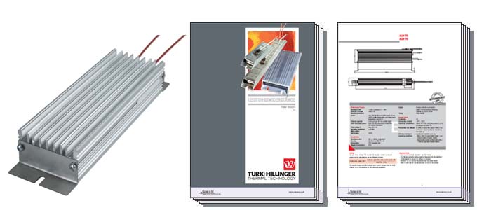
ALW 80

ALW 80 (PDF datasheet)Product enquiry and further information (Contact us form)
Resistance R20
- 1-1000 Ω, tolerance +/- 10%
Dielectric strength
- 4000 V DC
Short term peak power
- up to 300 kW depending on pulse time and resistor dimensions.
Pulse voltage U
- max 970 V DC
Insulation resistance
- ≥ 10 MΩ
Max. surface temperature
- 250°C
Resistance wire
- NiCr or similar composition
Housing
- Aluminium Profile 80 x 20
Connections
- PTFE insulated lead
Degree of protection
- IP23
Option
- Bimetal protector as protection against thermal overload (Breaking capacity e.g. 0,5 A/230 V)
Fixing
- directly with screws M5
Technical Data
- Short-term peak power W
- Nominal perm. power W
- Length
- Width x Height mm
- Thermal capacity kJ/K
- 5000
- 125
- 160
- 80 x 20
- 0,42
- 7000
- 140
- 240
- 80 x 20
- 0,68
- 9000
- 200
- 300
- 80 x 20
- 0,86
- 12000
- 270
- 400
- 80 x 20
- 1,22
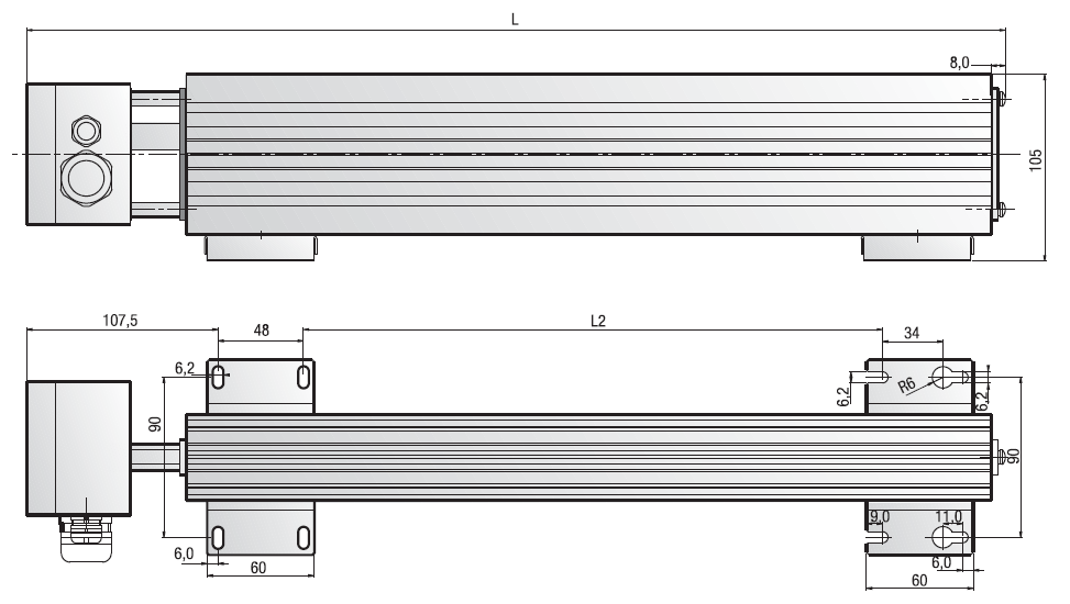
ALW 90
ALW 90 (PDF datasheet)Product enquiry and further information (Contact us form)
Resistance R20
- 1-1000 Ω, tolerance +/- 10%
Dielectric strength
- 4000 V DC
Nominal permanent power
- max. 130 W/100 mm profile length at max. 250°C profile temperature and environment temperature max. 45°C
Thermal capacity
- 0,43 kJ/K pro 100 mm profile length
Short term peak power
- up to 1.000 kW depending on pulse time and resistor dimensions
Pulse voltage U
- max. 970 V DC
Insulation resistance
- ≥ 10 MΩ
Max. surface temperature
- 250°C
Resistance wire
- NiCr or similar composition
Housing
- Aluminium profile 90 x 50
Connections
- Connection box with high-strength cable gland
Degree of protection
- IP65
Option
- Bimetal protector as protection against thermal overload (Breaking capacity e.g. 0,5 A/230 V)
Fixing
- fixing bracket
Special executions
- without bimetal protector
- without connection box, leads led out directly
Conformity
- CE
Permissible ambient
- -10°C…+55°C
Operating temperature
- (above 45°C the continuous power Pn is to be reduced by 2,5%/°C)
Permissible site altitude
- 0…4000 m above NN, (above 1000 m the continuous power Pn is to be reduced by 5%/1000 m)
Vibration resistance
- Acceleration resistant up to 1g
Mounting position
- Customer specific
Operating conditions
- Mean value of regenerative power < permanent power of power resistor
- Regenerative power during braking time < thermal capacity of brake resistor
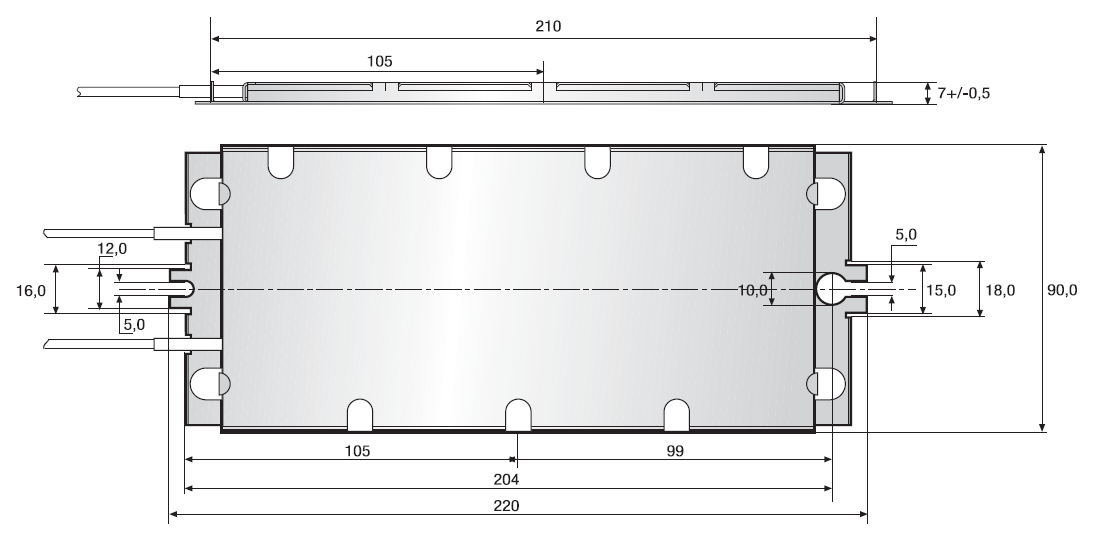
Flat Brake Resistor FBW
Flat Brake Resistor FBW (PDF datasheet)Product enquiry and further information (Contact us form)
The extremely flat profile of the FBW resistor enables installation in confined spaces. The large surface area enables the resistor even when used on frequent braking sequences to perform without overheating.
Resistance R20
- 1-1000 Ω, tolerance +/- 10%
Dielectric strength
- 4000 V DC
Pulse voltage U
- max. 970 V DC
Insulation resistance
- ≥ 10 MΩ
Max. surface temperature
- 350°C
Resistance wire
- NiCr or similar composition
Housing
- Aluminium profile 90 x 50
Connections
- Connection box with high-strength cable gland
Degree of protection
- IP65
- Type
- Nominal permanent power
- Max. short-term peak power
- Max. temperature at resistor in case of free convection and ambient temperature max. 45°C
- Available Dimensions
- Type A
- 35 W
- 10 kW
- 250°C
- 90x7x220 mm
- Type B
- 50 W
- 15 kW
- 250°C
- 90x7x250 mm
- Type C
- 100 W
- 30 kW
- 250°C
- 130x7x290 mm
Resistance wire
- NiCr or similar composition
Resistor core/insulation
- Micanite
Housing
- Zinc-plated steel
Connections
- PTFE insulated lead
Degree of protection
- IP20
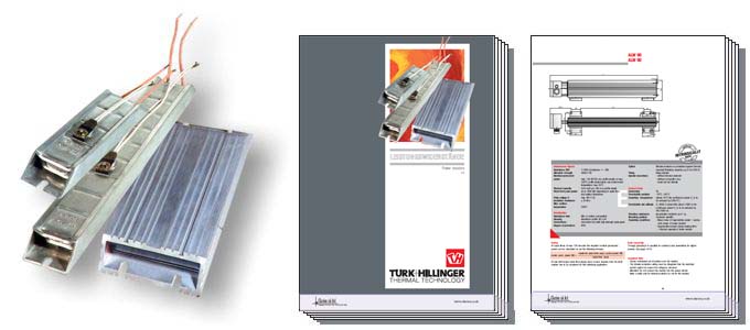
ALW 80/90 Rack Assembly
ALW 80/90 Rack Assembly (PDF datasheet)Product enquiry and further information (Contact us form)
ALW 80
For permanent wattages from 400 W to 800 W there are 2 or 3 ALW 80 resistors with an overall length of 300 mm or 400 mm mounted on sheet metal brackets and wired in parallel within a connection box. The permissible permanent or peak wattages are 2 to 3 times higher than the permissible wattages of the single resistors, as well as the other technical data.
The connection box is of protection degree IP 23.
The connection lead can be passed into the housing through a grommet.
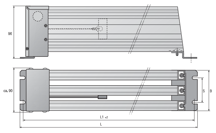
ALW 90
For higher power ranges the grouping of several ALW 90 is possible. The permissible permanent or peak wattages are calculated over the total profile length. The connection box is of protection degree IP 65, on request it is also possible to supply a lower protection degree.
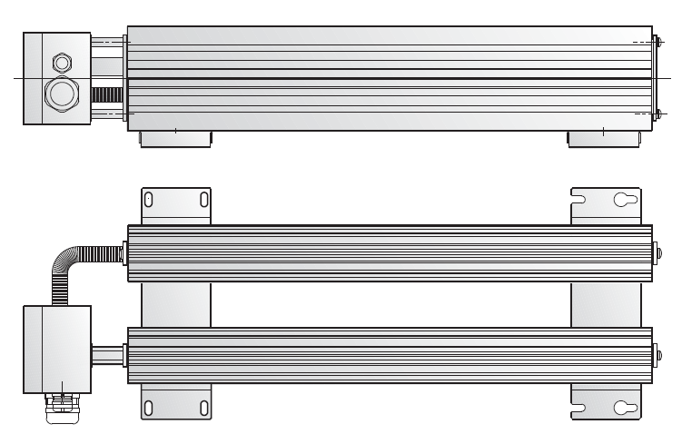
ALW 40/80 on Edge Mounting
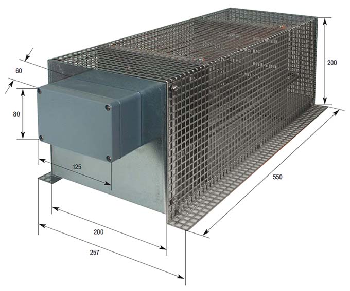
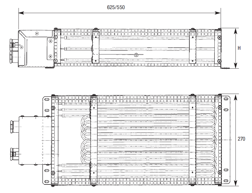
Power Resistor RHK
The RHK type power resistors are designed for the smoothing of performance peaks for electric and electronic circuits at permanent performances higher than 800 W (e. g. escalator controls) . These resistors consist of one or several tubular heaters ø 8,5 mm with a stainless steel sheath which are assembled into a housing of zinc plated perforated sheet metal. Upon request the resistors can be supplied with an optional thermostat to control the maximum sheath temperature of the resistors.
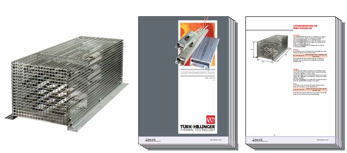
Power Resistor RHK (PDF datasheet)Product enquiry and further information (Contact us form)
For special cases of operation the power resistors type RHK can be supplied with an incorporated splash proof enclosure with protection degree IP 54. The resistors are wired in parallel.
Permanent power
- up to 10800 W (higher powers on request).
Dielectric strength
- 1800 V DC, with insulated mounting up to 4100 V DC available on request
Resistance R20
- 0,1 – 1.000 Ω
Permissible voltage
- 970 V DC
Resistor elements
- Tubular heaters ø 8,5 mm w-shape and assembled inside of a perforated sheet metal housing.
Protection Degrees
- IP 20, IP 54 or IP 64
Number of RHK heaters*
- up to 1000 W permanent power 1 heater
- up to 2400 W permanent power 2 heaters
- up to 3600 W permanent power 3 heaters
- up to 4800 W permanent power 4 heaters
- up to 7200 W permanent power 6 heaters
- up to 10800 W permanent power 9 heaters
Connection
- Ceramic terminal block inside the connection box cable gland on sheet metal housing for the assembly of a connection cable.
Wiring scheme
- The RHK heaters are connected in parallel with bridges between the heaters, connected with the terminal block.
* These are guiding values. The number of RHK can change subject to the individual operating conditions.
Product enquiry and further information
We would be delighted to offer free application advice, technical information on products, free quotations and delivery information.