- Home
- Thermal Management
- Heaters
- Aluminium Foil Heaters - IP68
- Cartridge Heaters
- Cast Heaters
- Ceramic Knuckle Heaters
- Coil Heaters, Coiled Heater Bands and Nozzle Heaters
- Custom Heaters
- Drum Heaters
- Finned Air Heaters
- Flanged Heaters
- Flat Tubular Heaters
- Flexible Tubular Heaters
- Heating Cables, Crankcase Heater
- Immersion Heaters
- Mica Insulated Heaters, Mica Band Heaters, Mica Plate Heaters
- PTC Self-regulating Heating Elements
- Silicone Mat Heaters, Wire Wound, Etched Foil
- Tape Heaters
- Thick Film Heating Elements
- Tubular Heaters
- Temperature sensors
- Temperature controllers
- Products
- Contact
R 2000 - 4 / 6 / 8 / 10 controller zones
- Option: heater current monitoring (3 phase)
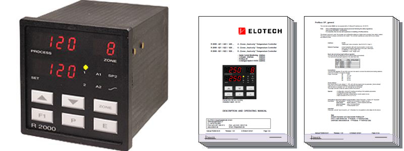
Clarian R2000 4 | 6 | 8 zone 2-point controller (PDF datasheet). Product enquiry and further information (Contact us form).
Clarian R2000 4 zone 3-point controller (PDF datasheet).
Technical Data
Input RTD, Pt 100 (DIN):
- 2 - or 3 - wire connection possible.
- Built-in protection against sensor breakage and short circuit.
- Max. permissible line resistance by 3-wire connection: 80 Ohms
- Sensor current: < 1 mA
- Calibration accuracy: < 0,2 %
- Linear error: < 0,2 %
- Influence of the ambient temperature: < 0,01 % / K
Input Thermocouple:
- Built-in internal compensation point and protection against sensor breakage and incorrect polarity.
- Re-calibration not required for a line resistance of up to 50 Ohms.
- Calibration accuracy: < 0,25%
Analog inputs (Option):
- 0 ... 10 V DC (Display range programmable)
Setpoint selection:
- Ext. potential-free contact, switching voltage appr. 24 V DC, max. 1 mA.
- Selection between SP1 and SP2 valid for all zones.
Control outputs OUT 1 ... OUT 8:
- Bist. voltage signal, 0/18 V DC, max. 10 mA, short-circuit proof
Alarm outputs A1 and A2:
- Relay, max. 250 V AC, max. 3 A (cos-phi = 1)
7-Segment-Display:
- Process: 10 mm red, Set: 10 mm red
Data protection:
- EAROM
CE-Mark
- Tested according to 2004/108/EC; EN 61326-1; industrial areas
- Electr. safety: EN 61010-1
Power supply:
- 115 / 230 / 24 V AC: ± 10%, 48...62 Hz; appr. 10VA 24 V DC: +/-25%
Connections:
- Screw terminals, Protection mode IP 20 (DIN 40050), Insulation class C
Permissible operating conditions:
- Operating temperature: 0...50 °C / 32...122 °F
- Storage temperature: -30...70 °C / -22...158 °F
- Climate class: KWF DIN 40040; equivalent to annual average max. 75 % rel. humidity, no condensation
Casing:
- Format: 96 x 96 mm (DIN 43700), installation depth 122 mm
- Panel cutout: 92 +0,5 mm x 92 +0,5 mm
- Material: Noryl, self-extinguishing, non-drip, UL 94-V1
- Protection mode: IP 20 (DIN 40050), IP 50 front side
Weight:
- app. 800 g
Heater current monitoring:
- Current transformer 1:1000:
(Type M2000)- Passive through current transformer with snap-in attachment for DIN rail mounting (EN 50022, 35mm).
- Connections to the controller: 2 x 6,3mm flat connectors.
- Heater current detection and indication range:
- 0...max. 60,0A. Single-phase operation.
- 0...max. 99,9 A. Three-phase operation.
- The sum of the current of all three phases of one controller zone will be monitored.
- Variations of the power supply voltage have to be considered when the the alarm values are programmed.
- Current detection interval time programmable (1...60 sec.).
- This is the time between the measuring of two successive controller zones.
- Alarm delay time programmable.
- It depends upon the current detection interval time and the number of the connected temperature zones (min. 8 sec.).
Subject to technical improvements
Product enquiry and further information
We would be delighted to offer free application advice, technical information on products, free quotations and delivery information.